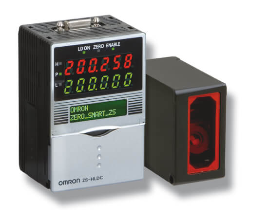
ZS-HL
Der skalierbare hochpräzise Laser-Messsensor für alle Oberflächen
Der intelligente Sensor ZS-HL bietet einen überragenden dynamischen Erfassungsbereich für Oberflächen aller Art, von schwarzem Gummi bis hin zu Glas und Spiegeloberflächen, indem er sich einfach an die Anforderungen der Anwendung anpasst. Er ergänzt die bestehende ZS - Sensorfamilie durch Köpfe mit größerer Reichweite sowie höherer Linearität.
- Höchste Auflösung und dynamischer Erfassungsbereich für alle Oberflächen
- Modulares und skalierbares Plattformkonzept für bis zu neun Sensoren
- Einfache Anwendung, Installation und Wartung
- Kurze Ansprechzeit: ab 110 µs
- Die Multitasking-Fähigkeit gestattet die gleichzeitige Verwendung von bis zu 4 Messmethoden in einem Controller
Spezifikationen & Bestellinfo
Ordering information
Sensors
ZS-HL-series sensor heads
|
Resolution1 |
|||||
|---|---|---|---|---|---|
ZS-HL-series sensor heads (for nozzle gaps) also compatible with ZS-L controller
|
Resolution2 |
|||||
|---|---|---|---|---|---|
ZS-L-series sensor heads
|
Resolution3 |
|||||
|---|---|---|---|---|---|
ZS-HL-series sensor controllers
Multi-controllers
Data storage units
Accessories (sold separately)
Controller link
Panel mount adapter
Cables for connecting to a Personal Computer
Extension cables for sensor heads
|
ZS-XC10B1 |
Logging software
Memory card
Safety precautions for using laser equipment

Specifications
Sensor heads
ZS-HL-series sensor heads
|
Visible semiconductor laser (wavelength: 650 nm, 1 mW max., JIS Clas |
Visible semiconductor laser (wavelength 658 nm, 1 mW max., Class 2) |
|||||||||
|
Beam diameter1 |
||||||||||
|
Linearity2 |
||||||||||
|
Resolution3 |
||||||||||
|
Temperature characteristic4 |
||||||||||
|
110 µs (high-speed mode), 500 µs (standard mode), 2.2 ms (high-precision mode), 4.4 ms (high-sensitivity mode) |
||||||||||
|
Lits near the measurement center, and nearer than the measurement center distance inside the measuring range. |
||||||||||
|
Lits near the measurement center, and further than the measurement center distance inside the measuring range. |
||||||||||
|
Illumination on received light surface 3,000 lx or less (incandescent light) |
Illumination on received light surface 1,000 lx or less (incandescent light) |
Illumination on received light surface 500 lx or less (incandescent light) |
||||||||
|
Operating: 0 to 50°C, storage: -15 to 60°C (with no icing or condensation) |
||||||||||
|
10 to 150 Hz, 0.7 mm double amplitude, 80 min each in X, Y, and Z directions |
||||||||||
|
150 m/s² 3 times each in six directions (up/down, left/right, forward/backward) |
||||||||||
*1 Defined as 1/e² (13.5%) of the center optical intensity in the measurement center distance. The beam diameter is sometimes influenced by the ambient conditions of the workpiece such as leaked light from the main beam.
*2 This is the error on the measured value with respect to an ideal straight line. Linear curve may change according to the workpiece. The following lists the workpieces
*3 This is the “peak-to-peak” displacement conversion value of the displacement output in the measurement center distance when high-resolution mode and the average number in the table are set (For ZS-HLDS60, the maximum resolution at 250 mm is also included). The following lists the workpieces.
*4 Value obtained when the sensor part and object part are fixed with an aluminum jig.
ZS-L-series sensor heads
|
Visible semiconductor laser (wavelength: 650 nm, 1 mW max., JIS Class 2) |
|||||||||
|
Beam diameter6 |
|||||||||
|
Linearity7 |
|||||||||
|
Resolution8 |
|||||||||
|
Temperature characteristic9 |
|||||||||
|
Sampling cycle10 |
110 µs (high-speed mode), 500 µs (standard mode), 2.2 ms (high-precision mode), 4.4 ms (high-sensitivity mode) |
||||||||
|
Lights near the measuring center distance, and nearer than the measuring center distance inside the measuring range. Flashes when the measurement target is outside of the measuring range or when the received light amount is insufficient. |
|||||||||
|
Lights near the measuring center distance, and further than the measuring center distance inside the measuring range. Flashes when the measurement target is outside of the measuring range or when the received light amount is insufficient. |
|||||||||
|
Illumination on received light surface: 3,000 lx or less (incandescent light) |
|||||||||
|
Operating: 0 to 50°C, storage: -15 to 60°C (with no icing or condensation) |
|||||||||
|
Laser labels (1 each for JIS/EN, 3 for FDA), ferrite cores (2), insure Locks (2), instruction sheet |
Laser safety labels (1 each for JIS/EN),ferrite cores (2), insure locks (2) |
||||||||
ZS-L-series sensor heads
|
Visible semiconductor laser (wavelength: 650 nm, 1 mW max., JIS Class 2) |
||||||||||||
|
Beam diameter11 |
||||||||||||
|
Linearity12 |
||||||||||||
|
Resolution13 |
||||||||||||
|
Temperature characteristic14 |
||||||||||||
|
Sampling cycle15 |
110 µs (high-speed mode), 500 µs (standard mode), 2.2 ms (high-precision mode), 4.4 ms (high-sensitivity mode) |
|||||||||||
|
Lights near the measuring center distance, and nearer than the measuring center distance inside the measuring range. Flashes when the measurement target is outside of the measuring range or when the received light amount is insufficient. |
||||||||||||
|
Lights near the measuring center distance, and further than the measuring center distance inside the measuring range. Flashes when the measurement target is outside of the measuring range or when the received light amount is insufficient. |
||||||||||||
|
Illumination on received light surface: 3,000 lx or less (incandescent light) |
Illumination on received light surface: 2,000 lx or less (incandescent light) |
Illumination on received light surface: 3,000 lx or less (incandescent light) |
||||||||||
|
Operating: 0 to 50°C, storage: -15 to 60°C (with no icing or condensation) |
||||||||||||
|
Laser labels (1 each for JIS/EN, 3 for FDA), ferrite cores (2), insure Locks (2), instruction sheet |
||||||||||||
Sensor controllers
ZS-HL-series sensor controllers
ZS-MDC11/MDC41 multi controllers
Basic specifications are the same as those for the sensor controllers.
The following points, however, are different.
(1) Sensor heads cannot be connected.
(2) A maximum 9 of controllers can be connected. Control link units are required to connect controllers.
(3) Processing functions between controllers: Math functions
Controller link unit

Data storage units
|
10 controllers max. (ZS-MDC: 1 controller, ZS-HLDC: 9 controllers max.)16 |
||||
|
Serial I/O: connector, other: pre-wired (standard cable length: 2 m) |
||||
|
3 outputs: HIGH, PASS, and LOW
NPN open-collector, 30 VDC, 50 mA max., |
3 outputs: HIGH, PASS, and LOW
PNP open-collector, 50 mA max., |
|||
|
ON: Short-circuited to supply voltage or within 1.5 V of supply voltage |
||||
|
Start and stop triggers can be set separately; external triggers, data triggers (self-triggers), and time triggers |
||||
|
External banks, alarm outputs, saved data format customization, and clock |
||||
|
16 digitsx2 rows, color of characters: green, resolution per character: 5x8 pixel matrix |
||||
|
Direction keys (UP, DOWN, LEFT, and RIGHT), SET key, ESC key, MENU key, and function keys (1 to 4) |
||||
|
Threshold switch (2 states: High/Low), mode switch (3 states: FUN, TEACH, and RUN) |
||||
|
Operating: 0 to 50°C, storage: -15 to 60°C (with no icing or condensation) |
||||
|
Ferrite core (1) instruction sheet, tools for data storage unit: CSV file converter for data storage unit, smart analyzer macro edition |
||||
3. This is the peak-to-peak displacement conversion value in the displacement output at the measuring center distance in high-precision mode when the number of samples to average is set to 128 and the measuring mode is set to the high-resolution mode. The standard workpiece is white aluminum ceramics in diffuse reflection mode and glass in the regular reflection mode.
6. Defined as 1/e² (13.5%) of the center optical intensity at the actual measurement center distance (effective value). The beam diameter is sometimes influenced by the ambient conditions of the workpiece, such as leaked light from the main beam.
7. This is the error in the measured value with respect to an ideal straight line. The standard workpiece is white aluminum ceramics in diffuse reflection mode and glass in the regular reflection mode of the ZS-LD20T/40T/50. Linearity may change according to the workpiece.
8. This is the peak-to-peak displacement conversion value in the displacement output at the measuring center distance in high-precision mode when the number of samples to average is set to 128 and the measuring mode is set to the high-resolution mode. The standard workpiece is white aluminum ceramics in diffuse reflection mode and glass in the regular reflection mode.
9. This is the value obtained at the measuring center distance when the Sensor and workpiece are fixed by an aluminum jig.
11. Defined as 1/e² (13.5%) of the center optical intensity at the actual measurement center distance (effective value). The beam diameter is sometimes influenced by the ambient conditions of the workpiece, such as leaked light from the main beam.
12. This is the error in the measured value with respect to an ideal straight line. The standard workpiece is white aluminum ceramics in diffuse reflection mode and glass in the regular reflection mode of the ZS-LD20T/40T/50. Linearity may change according to the workpiece.
13. This is the peak-to-peak displacement conversion value in the displacement output at the measuring center distance in high-precision mode when the number of samples to average is set to 128 and the measuring mode is set to the high-resolution mode. The standard workpiece is white aluminum ceramics in diffuse reflection mode and glass in the regular reflection mode.
*1 Defined as 1/e² (13.5%) of the center optical intensity in the measurement center distance. The beam diameter is sometimes influenced by the ambient conditions of the workpiece such as leaked light from the main beam.
*2 This is the error on the measured value with respect to an ideal straight line. Linear curve may change according to the workpiece. The following lists the workpieces
*3 This is the “peak-to-peak” displacement conversion value of the displacement output in the measurement center distance when high-resolution mode and the average number in the table are set (For ZS-HLDS60, the maximum resolution at 250 mm is also included). The following lists the workpieces.
3. This is the peak-to-peak displacement conversion value in the displacement output at the measuring center distance in high-precision mode when the number of samples to average is set to 128 and the measuring mode is set to the high-resolution mode. The standard workpiece is white aluminum ceramics in diffuse reflection mode and glass in the regular reflection mode.
6. Defined as 1/e² (13.5%) of the center optical intensity at the actual measurement center distance (effective value). The beam diameter is sometimes influenced by the ambient conditions of the workpiece, such as leaked light from the main beam.
7. This is the error in the measured value with respect to an ideal straight line. The standard workpiece is white aluminum ceramics in diffuse reflection mode and glass in the regular reflection mode of the ZS-LD20T/40T/50. Linearity may change according to the workpiece.
8. This is the peak-to-peak displacement conversion value in the displacement output at the measuring center distance in high-precision mode when the number of samples to average is set to 128 and the measuring mode is set to the high-resolution mode. The standard workpiece is white aluminum ceramics in diffuse reflection mode and glass in the regular reflection mode.
9. This is the value obtained at the measuring center distance when the Sensor and workpiece are fixed by an aluminum jig.
11. Defined as 1/e² (13.5%) of the center optical intensity at the actual measurement center distance (effective value). The beam diameter is sometimes influenced by the ambient conditions of the workpiece, such as leaked light from the main beam.
12. This is the error in the measured value with respect to an ideal straight line. The standard workpiece is white aluminum ceramics in diffuse reflection mode and glass in the regular reflection mode of the ZS-LD20T/40T/50. Linearity may change according to the workpiece.
13. This is the peak-to-peak displacement conversion value in the displacement output at the measuring center distance in high-precision mode when the number of samples to average is set to 128 and the measuring mode is set to the high-resolution mode. The standard workpiece is white aluminum ceramics in diffuse reflection mode and glass in the regular reflection mode.
Sie brauchen Unterstützung?
Wir helfen Ihnen gerne! Sprechen Sie uns an, und unsere Experten helfen Ihnen, die beste Lösung für Ihr Unternehmen zu finden.
Ihr Kontakt ZS-HL
Vielen Dank für Ihre Anfrage. Wir setzen uns umgehend mit Ihnen in Verbindung.
Es liegen zur Zeit technische Probleme vor. Ihre Übertragung war nicht erfolgreich. Entschuldigen Sie dies bitte und versuchen es später noch einmal. Details
DownloadAngebot für ZS-HL
Über dieses Formular erhalten Sie ein Angebot zu Ihrem ausgewählten Produkt. Bitte füllen Sie alle Felder aus, die diese * Markierung besitzen. Ihre persönlichen Daten werden natürlich vertraulich behandelt.

Vielen Dank für Ihre Angebots-Anfrage, die wir schnellstmöglich beantworten werden.
Es liegen zur Zeit technische Probleme vor. Ihre Übertragung war nicht erfolgreich. Entschuldigen Sie dies bitte und versuchen es später noch einmal. Details
DownloadFunktionen
Abstandsmessung – Scheibenoberfläche
Der Sensor überprüft auf stark reflektierenden Oberflächen durch Messen des exakten Abstands das Taumeln einer Scheibe.
Glasstärke – Windschutzscheibe
Der ZS ist in der Lage, mit nur einem Sensorkopf die Stärke von transparenten Objekten zu messen.
Höhenmessung – Klebstoffraupe
Der Sensor misst präzise die Höhe einer halbtransparenten Klebstoffraupe.
Stärkemessung – schwarzes Gummi
Der ZS misst mittels zweier Sensoren und einer Recheneinheit die Stärke von mattschwarzem, gummiähnlichem Material.
Prüfung der Planheit – Kolben
Mehrere Sensoren überprüfen die Planheit einer bearbeiteten, reflektierenden Oberfläche.
