Elektronischer Schutzschalter
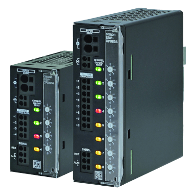
S8V-CP – Elektronischer Schutzschalter
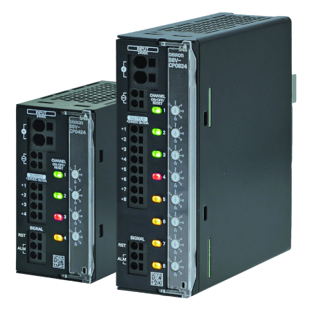
Der S8V-CP schützt Gleichstromkreise sehr präzise. Überlast und Kurzschlüsse werden genau erkannt und zuverlässig abgeschaltet.
- Elektronische 4/8-Kanal-Schutzschalter mit einstellbaren Auslöseströmen von 2 bis 10 A
- Thermomagnetisches Auslösen
- Sequenzieller und lastabhängiger Start der Ausgänge zur Vermeidung hoher Einschaltströme
- Hohe kapazitive Lasten können zuverlässig eingeschaltet werden.
- Hintergrundbeleuchtete Tasten mit mehrfarbigen LEDs zeigen den Ausgangsstatus auf einen Blick an.
- „Push-In Plus“-Anschlüsse
- Platzsparendes Value-Design für Schaltschrank
- Das UL-Modell der Klasse 2 reduziert die Kosten für die Anwendung eines Sicherheitsstandards.
Spezifikationen & Bestellinfo
Ordering information
Model Number Structure
Model Number Legend
Not all combinations are possible. Refer to List of Models in Ordering Information, below.

(1) Number of Outputs
| Code | Number of Outputs |
|---|---|
| 04 | 4 outputs |
| 08 | 8 outputs |
(2) Rated input voltage
| Code | Rated input voltage |
|---|---|
| 24 | 24 VDC |
(3) UL Class 2 output
| Code | UL Class 2 output certified |
|---|---|
| S | Yes |
| No | No |
List of Models
Unit
| Number of Outputs | UL Class 2 output | Order code |
|---|---|---|
| 4 outputs | No | S8V-CP0424 |
| Yes | S8V-CP0424S | |
| 8 outputs | No | S8V-CP0824 |
Specifications
| Item | Model Number of Outputs UL Class 2 output | S8V-CP0424 | S8V-CP0424S | S8V-CP0824 | |
|---|---|---|---|---|---|
| 4 | 4 | 8 | |||
| No | Yes | No | |||
| I/O characteristics | Rated input voltage (Input voltage allowable range) | 24 VDC (20 to 30 VDC) | 24 VDC (20 to 28.8 VDC) | 24 VDC (20 to 30 VDC) | |
| Allowable
input current
2
For power input terminals, use 35 A max. per pole. |
40 A | 15.2 A | 70 A | ||
| Max. rated output current (per output) | 10 A | 3.8 A | 10 A | ||
| Internal
voltage drop
2
A voltage drop will occur in the S8V-CP. Consider
the voltage drop at the output. |
200 mV max. | 150 mV max. | 200 mV max. | ||
| Output leakage current | 10 mA max. | ||||
| Power consumption
2
When
selecting the power supply, be sure to include the internal power
consumption of the S8V-CP and not just the power consumption of
the load. |
When all outputs are connected |
10 W max. (at 10 A) | 3.1 W max. (at 3.8 A) | 20 W max. (at 10 A) | |
| When all output branches are tripped |
0.84 W typ. | 0.82 W typ. | 1.32 W typ. | ||
| Start-up
time
2
Outputs start in order from +VO1 to +VO8. +VO1 starts after
the initialization time. Start-up delay time of each output is automatically
decided depending on the load. If the start-up delay time is over
5 s, the next output is forcibly started. |
Initialization time | 250 ms typical | |||
| Start-up delay time | 50 ms to 5 s | ||||
| Functions
2
Refer
to Cat. No. T226-E1 for details. |
Current
tripping function
2
Refer to Cat. No. T226-E1
for details. |
Rated output current | 2 A, 3 A, 4 A, 6 A, 8 A, 10 A | 3.8 A | 2 A, 3 A, 4 A, 6 A, 8 A, 10 A |
| Cutoff current | 2.5 A, 3.5 A, 4.5 A, 6.5 A, 8.5 A, 10.5 A |
3.8 A | 2.5 A, 3.5 A, 4.5 A, 6.5 A, 8.5 A, 10.5 A |
||
| Over voltage
tripping function
2
Refer to Cat. No. T226-E1
for details. |
No | Yes | No | ||
| Push button (ON/OFF/RESET) with indicator | Yes (LED colors: Red/Green/Yellow) | ||||
| Reset signal input (RST) | Yes (High level: 15 to 30 VDC, Low level: 0 to 5 VDC) | ||||
| Alarm signal output (ALM1/ALM2) | Yes (MOS FET relay output 30 VDC max., 50 mA max.) | ||||
| Insulation | Dielectric strength | 1.0 kVAC for 1 min (between all terminals and DIN rail mounting parts), current cutoff 20 mA | |||
| Insulation resistance | 100 MΩ min. (between all terminals and DIN rail mounting parts) at 500 VDC | ||||
| Environment | Ambient operating temperature | –25 to 70°C (Derating is required according to the temperature.) (with no condensation or icing) | |||
| Storage temperature | –40 to 85°C (with no condensation or icing) | ||||
| Ambient operating humidity | 5% to 96% (storage humidity: 5% to 96%) | ||||
| Vibration resistance | 10 to 55 Hz, maximum 5 G, 0.42 mm half amplitude for 2 h each in X, Y, and Z directions | ||||
| Shock resistance | 294 m/s2, 3 times each in ±X, ±Y, ±Z directions | ||||
| Reliability | MTBF
2
MTBF
is calculated according to JEITA RCR-9102. |
13,5000 hrs typ. | 60,000 hrs typ. | 13,5000 hrs typ. | |
| Life expectancy
2
Refer
to Cat. No. T226-E1 for details. |
10 years min. | ||||
| Construction | Weight | 160 g max. | 170 g max. | 420 g max. | |
| Cooling fan | No | ||||
| Degree of protection | IP20 by EN/IEC 60529 | ||||
| Standards | EMI | Conforms to EN 61000-6-3 | |||
| EMS | Conforms to EN 61000-6-2 | ||||
| Safety standards | UL 508 (CSA22.2 No.14-10) Listing Pol2 UL 2367 Recognition (Max. 100W per output, per Class 2 limitations) Pol2
2
UL Class 2 output applies for the S8V-CP0424S model only. CE (EN 61000-6-2, EN 61000-6-3) |
||||
Sie brauchen Unterstützung?
Wir helfen Ihnen gerne! Sprechen Sie uns an, und unsere Experten helfen Ihnen, die beste Lösung für Ihr Unternehmen zu finden.
Ihr Kontakt Elektronischer Schutzschalter
Vielen Dank für Ihre Anfrage. Wir setzen uns umgehend mit Ihnen in Verbindung.
Es liegen zur Zeit technische Probleme vor. Ihre Übertragung war nicht erfolgreich. Entschuldigen Sie dies bitte und versuchen es später noch einmal. Details
DownloadAngebot für Elektronischer Schutzschalter
Über dieses Formular erhalten Sie ein Angebot zu Ihrem ausgewählten Produkt. Bitte füllen Sie alle Felder aus, die diese * Markierung besitzen. Ihre persönlichen Daten werden natürlich vertraulich behandelt.

Vielen Dank für Ihre Angebots-Anfrage, die wir schnellstmöglich beantworten werden.
Es liegen zur Zeit technische Probleme vor. Ihre Übertragung war nicht erfolgreich. Entschuldigen Sie dies bitte und versuchen es später noch einmal. Details
Download