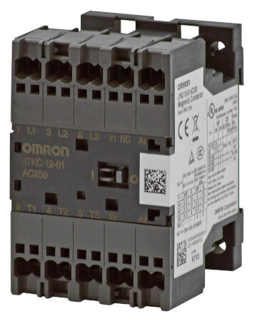
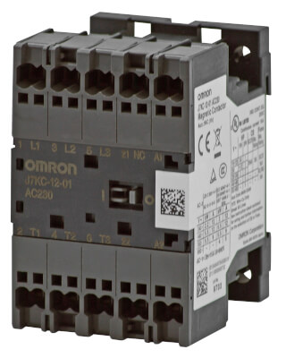
J7KC
Magnetschütz
Beste Lösung für Motor- und Primärseitenschalter mit bis zu 2,2 kW (240 VAC) *2; 5,5 kW (440 VAC)
- Geringere Verdrahtungs- und Wartungszeit dank Push-in-Plus-Anschlüssen
- Weltweit kleinste Größe *1
- Ideal für Motorsteuerung bis zu 2,2 kW (200 bis 240 VAC)*2; 5,5 kW (380 bis 440 VAC), AC-3-Klasse
- Hohe Kontaktzuverlässigkeit (min. 5 VDC, 3 mA)
- Spulenüberspannungsabsorber standardmäßig installiert*3
- Zertifiziert gemäß den wichtigsten Sicherheitsstandards
*1. Nach Untersuchungen von OMRON, Stand August 2019. Für Push-In-Modelle.
*2. Gemäß JIS C 8201-4-1
*3. DC-betrieben
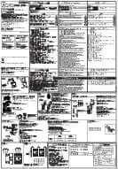
Spezifikationen & Bestellinfo
Ordering Information
Main unit
Product Type | Operation | Coil rating | Auxiliary contact | Order code |
---|---|---|---|---|
Magnetic contactor | AC-operated | 24 VAC | SPST-1NO | J7KC-12-10 AC24 |
SPST-1NC | J7KC-12-01 AC24 | |||
48 VAC | SPST-1NO | J7KC-12-10 AC48 | ||
SPST-1NC | J7KC-12-01 AC48 | |||
100 VAC | SPST-1NO | J7KC-12-10 AC100 | ||
SPST-1NC | J7KC-12-01 AC100 | |||
110 VAC | SPST-1NO | J7KC-12-10 AC110 | ||
SPST-1NC | J7KC-12-01 AC110 | |||
120 VAC | SPST-1NO | J7KC-12-10 AC120 | ||
SPST-1NC | J7KC-12-01 AC120 | |||
200 VAC | SPST-1NO | J7KC-12-10 AC200 | ||
SPST-1NC | J7KC-12-01 AC200 | |||
220 VAC | SPST-1NO | J7KC-12-10 AC220 | ||
SPST-1NC | J7KC-12-01 AC220 | |||
230 VAC | SPST-1NO | J7KC-12-10 AC230 | ||
SPST-1NC | J7KC-12-01 AC230 | |||
240 VAC | SPST-1NO | J7KC-12-10 AC240 | ||
SPST-1NC | J7KC-12-01 AC240 | |||
380 VAC | SPST-1NO | J7KC-12-10 AC380 | ||
SPST-1NC | J7KC-12-01 AC380 | |||
400 VAC | SPST-1NO | J7KC-12-10 AC400 | ||
SPST-1NC | J7KC-12-01 AC400 | |||
440 VAC | SPST-1NO | J7KC-12-10 AC440 | ||
SPST-1NC | J7KC-12-01 AC440 | |||
500 VAC | SPST-1NO | J7KC-12-10 AC500 | ||
SPST-1NC | J7KC-12-01 AC500 | |||
DC-operated (With built-in surge absorption unit) |
12 VDC | SPST-1NO | J7KC-12-10 DC12 | |
SPST-1NC | J7KC-12-01 DC12 | |||
24 VDC | SPST-1NO | J7KC-12-10 DC24 | ||
SPST-1NC | J7KC-12-01 DC24 | |||
48 VDC | SPST-1NO | J7KC-12-10 DC48 | ||
SPST-1NC | J7KC-12-01 DC48 | |||
60 VDC | SPST-1NO | J7KC-12-10 DC60 | ||
SPST-1NC | J7KC-12-01 DC60 | |||
100 VDC | SPST-1NO | J7KC-12-10 DC100 | ||
SPST-1NC | J7KC-12-01 DC100 | |||
110 VDC | SPST-1NO | J7KC-12-10 DC110 | ||
SPST-1NC | J7KC-12-01 DC110 | |||
120 VDC | SPST-1NO | J7KC-12-10 DC120 | ||
SPST-1NC | J7KC-12-01 DC120 | |||
200 VDC | SPST-1NO | J7KC-12-10 DC200 | ||
SPST-1NC | J7KC-12-01 DC200 | |||
210 VDC | SPST-1NO | J7KC-12-10 DC210 | ||
SPST-1NC | J7KC-12-01 DC210 | |||
220 VDC | SPST-1NO | J7KC-12-10 DC220 | ||
SPST-1NC | J7KC-12-01 DC220 |
Product Type | Operation | Coil rating | Auxiliary contact | Order code |
---|---|---|---|---|
Reversing magnetic contactor |
AC-operated | 24 VAC | SPST-1NO | J7KCR-12-10 AC24 |
SPST-1NC | J7KCR-12-01 AC24 | |||
48 VAC | SPST-1NO | J7KCR-12-10 AC48 | ||
SPST-1NC | J7KCR-12-01 AC48 | |||
100 VAC | SPST-1NO | J7KCR-12-10 AC100 | ||
SPST-1NC | J7KCR-12-01 AC100 | |||
110 VAC | SPST-1NO | J7KCR-12-10 AC110 | ||
SPST-1NC | J7KCR-12-01 AC110 | |||
120 VAC | SPST-1NO | J7KCR-12-10 AC120 | ||
SPST-1NC | J7KCR-12-01 AC120 | |||
200 VAC | SPST-1NO | J7KCR-12-10 AC200 | ||
SPST-1NC | J7KCR-12-01 AC200 | |||
220 VAC | SPST-1NO | J7KCR-12-10 AC220 | ||
SPST-1NC | J7KCR-12-01 AC220 | |||
230 VAC | SPST-1NO | J7KCR-12-10 AC230 | ||
SPST-1NC | J7KCR-12-01 AC230 | |||
240 VAC | SPST-1NO | J7KCR-12-10 AC240 | ||
SPST-1NC | J7KCR-12-01 AC240 | |||
380 VAC | SPST-1NO | J7KCR-12-10 AC380 | ||
SPST-1NC | J7KCR-12-01 AC380 | |||
400 VAC | SPST-1NO | J7KCR-12-10 AC400 | ||
SPST-1NC | J7KCR-12-01 AC400 | |||
440 VAC | SPST-1NO | J7KCR-12-10 AC440 | ||
SPST-1NC | J7KCR-12-01 AC440 | |||
500 VAC | SPST-1NO | J7KCR-12-10 AC500 | ||
SPST-1NC | J7KCR-12-01 AC500 | |||
DC-operated (With built-in surge absorption unit) |
12 VDC | SPST-1NO | J7KCR-12-10 DC12 | |
SPST-1NC | J7KCR-12-01 DC12 | |||
24 VDC | SPST-1NO | J7KCR-12-10 DC24 | ||
SPST-1NC | J7KCR-12-01 DC24 | |||
48 VDC | SPST-1NO | J7KCR-12-10 DC48 | ||
SPST-1NC | J7KCR-12-01 DC48 | |||
60 VDC | SPST-1NO | J7KCR-12-10 DC60 | ||
SPST-1NC | J7KCR-12-01 DC60 | |||
100 VDC | SPST-1NO | J7KCR-12-10 DC100 | ||
SPST-1NC | J7KCR-12-01 DC100 | |||
110 VDC | SPST-1NO | J7KCR-12-10 DC110 | ||
SPST-1NC | J7KCR-12-01 DC110 | |||
120 VDC | SPST-1NO | J7KCR-12-10 DC120 | ||
SPST-1NC | J7KCR-12-01 DC120 | |||
200 VDC | SPST-1NO | J7KCR-12-10 DC200 | ||
SPST-1NC | J7KCR-12-01 DC200 | |||
210 VDC | SPST-1NO | J7KCR-12-10 DC210 | ||
SPST-1NC | J7KCR-12-01 DC210 | |||
220 VDC | SPST-1NO | J7KCR-12-10 DC220 | ||
SPST-1NC | J7KCR-12-01 DC220 |
Options (Order Separately)
Auxiliary contact unit
Number of poles | Auxiliary contact | Order code |
---|---|---|
2 poles | 2PST-2NO | J73KC-AM-20 |
2PST-1NO 1NC | J73KC-AM-11 | |
2PST-2NC | J73KC-AM-02 | |
4 poles | 4PST-4NO | J73KC-AM-40 |
4PST-3NO 1NC | J73KC-AM-31 | |
4PST-2NO 2NC | J73KC-AM-22 | |
4PST-1NO 3NC | J73KC-AM-13 | |
4PST-4NC | J73KC-AM-04 |
Interlock unit
Order code |
---|
J74KC-A |
Reversing conductor kit
Type | Order code |
---|---|
For main circuit | J75KC-WKR-A |
For auxiliary circuit | J75KC-WKR-B |
Coil surge absorption unit
Adopted Coil voltage type | LED indicator | Order code |
---|---|---|
24-48 VAC | No | J76KC-RC-1 |
48-125 VAC | J76KC-RC-2 | |
100-250 VAC | J76KC-RC-3 | |
24-48 VAC | Yes | J76KC-RC-N-1 |
48-125 VAC | J76KC-RC-N-2 |
Insulation stop
Minimum order (bag) | Order code |
---|---|
1 (30 pcs./bag) |
J77KC-K |
Tools for removal
Order code |
---|
J78KC |
Specifications
The ratings/specifications are the same for both non-reversing/reversing types.
Coil rating
AC operated
Displayed model | Rated voltage | Allowable voltage range | Must operate voltage | Must release voltage | |||
---|---|---|---|---|---|---|---|
50 Hz | 60 Hz | 50 Hz | 60 Hz | ||||
AC 24 | 24 VAC | 24-26 VAC | 85 to 110% | 21-27 VAC | 21-29 VAC | 85% max. | 20% min. |
AC 48 | 48 VAC | 48-52 VAC | 41-53 VAC | 41-58 VAC | |||
AC 100 | 100 VAC | 100-110 VAC | 85-110 VAC | 85-121 VAC | |||
AC 110 | 100-110 VAC | 110-120 VAC | 85-121 VAC | 94-132 VAC | |||
AC 120 | 110-120 VAC | 120-130 VAC | 94-132 VAC | 102-143 VAC | |||
AC 200 | 200 VAC | 200-220 VAC | 170-220 VAC | 170-242 VAC | |||
AC 220 | 200-220 VAC | 220-240 VAC | 170-242 VAC | 187-264 VAC | |||
AC 230 | 220-230 VAC | 230 VAC | 187-253 VAC | 196-253 VAC | |||
AC 240 | 220-240 VAC | 240-260 VAC | 187-264 VAC | 204-286 VAC | |||
AC 380 | 346-380 VAC | 380-420 VAC | 295-418 VAC | 323-462 VAC | |||
AC 400 | 380-400 VAC | 400-440 VAC | 323-440 VAC | 340-484 VAC | |||
AC 440 | 415-440 VAC | 440-480 VAC | 353-484 VAC | 374-528 VAC | |||
AC 500 | 480-500 VAC | 500-550 VAC | 408-550 VAC | 425-605 VAC |
DC operated
Displayed model | Rated voltage | Allowable voltage range | Must operate voltage | Must release voltage | |
---|---|---|---|---|---|
DC 12 | 12 VDC | 85 to 110% | 11-14 VDC | 85% max. | 10% min. |
DC 24 | 24 VDC | 21-27 VDC | |||
DC 48 | 48 VDC | 41-53 VDC | |||
DC 60 | 60 VDC | 51-66 VDC | |||
DC 100 | 100 VDC | 85-110 VDC | |||
DC 110 | 110 VDC | 94-121 VDC | |||
DC 120 | 120 VDC | 102-132 VDC | |||
DC 200 | 200 VDC | 170-220 VDC | |||
DC 210 | 210 VDC | 179-231 VDC | |||
DC 220 | 220 VDC | 187-242 VDC |
Coil characteristics (reference value)
AC operated
Frequency | 50 Hz | 60 Hz | |
Coil power consumption |
Making (VA) | 22 (200 V) | 25 (220 V) |
Holding (VA) | 4.5 (200 V) | 4.5 (220 V) | |
Power loss (W) | 1.2 (200 V) | 1.3 (220 V) | |
Must operate voltage (V) | 122 to 135 | 128 to 138 | |
Must release voltage (V) | 80 to 89 | 83 to 96 | |
Operate time (ms) | 17 to 26 | ||
Release time (ms) | 6 to 16 |
- Coil ratings: Characteristics for 200 VAC, 50 Hz / 200-220 VAC, 60 Hz.
- Coil power consumption value is the same for a coil that is not rated 200 VAC.
- Indicated operate/release times for 200 VAC, 50 Hz.
- Closed and open voltages of 100 V coil (100 VAC, 50 Hz/100-110 VAC, 60 Hz) are approximately one half the values in the table above.
- Values in the table above are examples for 20°C cold condition.
DC operated
Coil power consumption |
Making (W) | 2.4 (24 V) |
Holding (W) | 2.2 (24 V) | |
Time constant (ms) | Holding | 20 |
Must operate voltage (V) | 10 to 11 | |
Must release voltage (V) | 4 to 6 | |
Operate time (ms) | 34 to 60 | |
Release time (ms) | 5 to 10 |
- Coil ratings: Characteristics for 24 VDC.
- Coil power consumption value is the same for a coil that is not rated 24 VDC.
- Values in the table above are examples for 20°C cold condition.
Characteristics
Main circuit rating | Rating based on IEC 60947-4-1 |
AC-1 (Resistive load) |
Voltage range (V) | AC200-240 AC | AC380-440 AC | |||
Rated operational current (A) | 15 | 15 | ||||||
AC-3 (3-phase cage motor) |
Voltage range (V) | 200-240 AC | 380-440 AC | 500-550 AC | 600-690 AC | |||
Rated capacity (kW) | 3 | 5.5 | 5.5 | 4 | ||||
Rated operational current (A) | 12 | 12 | 9 | 5 | ||||
AC-4 (3-phase cage motor) |
Voltage range (V) | 200-240 AC | 380-440 AC | 500-550 AC | 600-690 AC | |||
Rated capacity (kW) | 3 | 5.5 | 5.5 | 4 | ||||
Rated operational current (A) | 12 | 12 | 9 | 5 | ||||
DC-1 (Resistive load L/R ≤ 1 ms) |
Voltage range (V) | 24 DC | 48 DC | 110 DC | 220 DC | |||
Rated operational current (A) |
Number of serial contacts 1 |
12 | 12 | 3 | 0.7 | |||
Number of serial contacts 2 |
12 | 12 | 9 | 4 | ||||
Number of serial contacts 3 |
12 | 12 | 12 | 12 | ||||
DC-3, DC-5 (DC motor load L/R ≤ 15 ms) |
Voltage range (V) | 24 DC | 48 DC | 110 DC | 220 DC | |||
Rated operational current (A) |
Number of serial contacts 1 |
2 | 1.5 | 1 | 0.1 | |||
Number of serial contacts 2 |
10 | 3 | 0.85 | 0.35 | ||||
Number of serial contacts 3 |
12 | 6 | 1.7 | 0.7 | ||||
Conventional free air thermal current (rated flowing current) (A) |
15 | |||||||
Rating based on UL 60947-4-1, CSA C22.2 |
3-phase motor | Voltage range (V) | 200 AC | 220-240 AC | 440-480 AC | 550-600 AC | ||
Rated capacity (HP) | 3 | 3 | 5 | 5 | ||||
Rated operational current (A) | 11 | 9.6 | 7.6 | 6.1 | ||||
Rated current (A) | 15 | |||||||
Single-phase motor |
Voltage range (V) | 110-120 AC | ||||||
Rated capacity (HP) | 3/4 | |||||||
Rated operational current (A) | 13.8 | |||||||
Rated current (A) | 15 | |||||||
FUSE | 30A (Class K5, RK5) | |||||||
Rating based on JIS C 8201-4-1 |
AC-1 (resistive load) |
Voltage range (V) | 200-240 AC | 380-440 AC | ||||
Rated operational current (A) | 15 | 15 | ||||||
AC-3 (3-phase cage motor) |
Voltage range (V) | 200-240 AC | ||||||
Rated capacity (kW) | 2.2 | |||||||
Rated operational current (A) | 12 | |||||||
DC-1 (Resistive load L/R ≤ 1 ms) |
Voltage range (V) | 24 DC | 48 DC | 110 DC | 220 DC | |||
Rated operational current (A) |
Number of serial contacts 1 |
12 | 12 | 3 | 0.7 | |||
Number of serial contacts 2 |
12 | 12 | 9 | 4 | ||||
Number of serial contacts 3 |
12 | 12 | 12 | 12 | ||||
DC-3, DC-5 (DC motor load L/R ≤ 15 ms) |
Voltage range (V) | 24 DC | 48 DC | 110 DC | 220 DC | |||
Rated operational current (A) |
Number of serial contacts 1 |
2 | 1.5 | 1 | 0.1 | |||
Number of serial contacts 2 |
10 | 3 | 0.85 | 0.35 | ||||
Number of serial contacts 3 |
12 | 6 | 1.7 | 0.7 | ||||
Conventional free air thermal current (rated flowing current) (A) |
15 | |||||||
Minimum operate voltage/current (reference value) | 24 VDC 10 mA | |||||||
Electrical/ mechanical endurance |
Voltage range (V) | 220 AC | 440 AC | |||||
Rated operational current (A) | 12 | 12 | ||||||
Contact closed current (A) | 144 | 144 | ||||||
Breaking current (A) | 120 | 120 | ||||||
Switching frequency (times per hour) | 1800 | 1800 | ||||||
Endurance (10,000 operations min.) |
Mechanical | 1000 | 1000 | |||||
Electrical (AC3) | 100
2
The electrical endurance
is the value at 200 V based on the electrical endurance test conditions
assumed in the IEC/JIS standards, and will vary depending on the
characteristics and load conditions of the motor you use. A large
motor starting current may cause a decrease of electrical endurance
or contact sticking. |
|||||||
Contact resistance (reference value) | 10 mΩ max. (6 VDC, 1 mA, voltage drop method) |
Auxiliary circuit rating |
Rating based on IEC 60947-5-1/ JIS C 8201-5-1 |
Voltage range (V) | 100-120 AC | 200-240 AC | 380-440 AC | 500-600 AC | 24 DC | 48 DC | 110 DC | 220 DC | ||
Rated operational current (A) | AC-15 (coil load) | DC-13 (coil load) | ||||||||||
3 | 3 | 1 | 0.5 | 2 | 1 | 0.3 | 0.2 | |||||
AC-12 (resistive load) | DC-12 (resistive load) | |||||||||||
6 | 6 | 6 | 3 | 3 | 2 | 1.5 | 0.5 | |||||
Contact closed and breaking current (A) | 30 | 30 | 10 | 5 | 30 | 30 | 10 | 5 | ||||
Conventional free air thermal current (rated flowing current) (A) |
10 | |||||||||||
Rating based on UL 508 |
Rated carry current (A) | 10 | ||||||||||
Voltage range (V) | 120 AC | 600 AC | ||||||||||
Contact closed current (A) | 60 | 12 | ||||||||||
Breaking current (A) | 6 | 1.2 | ||||||||||
Rating code | A 600 | |||||||||||
Minimum operate voltage/current (reference value) | 3 mA at 5 VDC | |||||||||||
Electrical/ mechanical endurance |
Switching frequency (times per hour) | 1800 | ||||||||||
Mechanical (10,000 cycles min.) | 1000 | |||||||||||
Electrical (10,000 cycles min.) |
AC-15 | 220 V | 50 | |||||||||
440 V | 50 | |||||||||||
AC-12 | 220 V | 25 | ||||||||||
440 V | 25 | |||||||||||
DC-13 | 220 V | 15 | ||||||||||
DC-12 | 220 V | 50 | ||||||||||
Contact resistance (reference value) | 50 mΩ max. (6 VDC, 1 mA, voltage drop method) | |||||||||||
Rated insulation voltage | 690 VAC | |||||||||||
Rated impulse dielectric strength | 6 kV | |||||||||||
Rated frequency | 50/60 Hz | |||||||||||
Vibration resistance | Vibration: 10 to 55 Hz, acceleration: 15 m/s2 | |||||||||||
Shock resistance | Shock value 50 m/s2 | |||||||||||
Contact form | Double break form (main circuit: single contacts, auxiliary circuit: bifurcated contacts) | |||||||||||
Contact material | Ag alloy | |||||||||||
Degree of protection | IP20 (IEC60529) | |||||||||||
Operating temperature | −10 to +55°C (however, daily average shall not exceed 35°C) | |||||||||||
Ambient storage temperature | −40 to +65°C (no condensation or icing) | |||||||||||
Relative humidity | 45% to 85% RH (no condensation or icing) | |||||||||||
Altitude | 2000 m max. | |||||||||||
Weight | 160 g (J7KC- |
|||||||||||
Applicable Standards | Safety standard | EN 60947-4-1(IEC 60947-4-1), UL 60947-4-1, CSA 22.2 No.60947-4-1, CCC GB/T14048.4 |
Wie können wir Ihnen helfen?
Wenn Sie eine Frage haben oder ein Angebot anfordern möchten, kontaktieren Sie uns oder senden Sie eine Anfrage.
Ihr Kontakt J7KC

Vielen Dank für Ihre Anfrage. Wir setzen uns umgehend mit Ihnen in Verbindung.
Es liegen zur Zeit technische Probleme vor. Ihre Übertragung war nicht erfolgreich. Entschuldigen Sie dies bitte und versuchen es später noch einmal. Details
DownloadAngebot für J7KC
Über dieses Formular erhalten Sie ein Angebot zu Ihrem ausgewählten Produkt. Bitte füllen Sie alle Felder aus, die diese * Markierung besitzen. Ihre persönlichen Daten werden natürlich vertraulich behandelt.

Vielen Dank für Ihre Angebots-Anfrage, die wir schnellstmöglich beantworten werden.
Es liegen zur Zeit technische Probleme vor. Ihre Übertragung war nicht erfolgreich. Entschuldigen Sie dies bitte und versuchen es später noch einmal. Details
Download